
RBF Morph took part in the 48th edition of the Italian Conference AIAS 2019 which was held on September, from 4th to 7th in Assisi (Italy).
Three works about the different applications of RBF Morph technology was presented:
Optimisation of industrial parts by mesh morphing enabled automatic shape sculpting
In this paper we explore how the last approach can be exploited according to two different strategies: the biological growth method (BGM), which consists in adding/removing material according to the local stress at surface, the adjoint method, which consists in moving inward outward the surface according to the surface sensitivities. The FEA solver ANSYS® MechanicalTM in combination with the mesh morphing software RBF MorphTM was adopted forthis purpose. The BGM implementation is the one implemented in RBF Morph, the adjoint solver is the one implemented in the topological optimisation tool by ANSYS. Automatic shape sculpting applications are demonstrated on a simple geometry, a thick plate with simple load conditions, andon an industrial part.
Multiphysics numerical investigation on the aeroelastic stability of a Le Mans Prototype car
In this paper, the flutter analysis of the front wing splitter mounted on the 2001 Le Mans Prototype car by Dallara (LMP1) is presented. The study was set up adopting high fidelity CAE models: a 400k shell elements FEM represents the full front wing assembly including the mounting frame, a 240M cells CFD represents the full car immersed in a box shaped wind tunnel. FEM extracted structural modal shapes are mapped onto the CFD mesh adopting Radial Basis Functions (RBF) mesh morphing so that the surfaces of the CFD model can be deformed according to retained modes. Such deformation is then propagated so that the volume mesh is adapted accordingly.
The elastic CFD model with modes embedded was then loaded by applying a transient signal individually to each retained mode with a smoothed step function. A Reduced Order Model (ROM) for the aerodynamics of the coupled system was then extracted combining the results of the individual transient run. The critical speed experimentally observed to be in the operating range of the car was captured by the model quite well. The same workflow was then adopted to investigate a different design in which a stiffener has been introduced to increase the first mode natural frequency from 40Hz to 49.4Hz. Flutter speed was increased and moved outside the vehicle range. The car equipped with the improved part proved to perform on the track without previously detected stabilities.
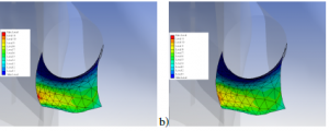
CAEU p – Update of CAE models on actual manufactured shapes
CAEUp aims at implementing a cloud-based software tool whose core is the comparison of the structural performances between the CAE model relative to the nominal design of a certain product and the digital twin of the real product as built. The digital twin is updated on HPC cloud infrastructure and the performance prediction recomputed adopting a variation of the CAE model shaped like the actual manufactured part. The process is demonstrated adopting a specific example: the structural assessment of a simplified turbine blade geometry. The baseline geometry, available as a CAD model, is adopted to define the reference FEA model for the ANSYS® MechanicalTM solver so that key performance indexes can be computed (stress level and stiffness). The actual manufactured shape is surveyed and available as a tesselated surface (the standard STL format is herein adopted). The projection and adaption using mesh morphing allows to morph the baseline FEA model onto the actual manufactured shape; finally the updated FEA model is run again to extract performance indexes and decide whether the component fulfills the design specifications.