
Multi-objective CFD Optimisation of Film cooling Turbine Blade Geometry with Mesh Morphing
 A Computational Fluid Dynamics (CFD) optimisation of a single row of film cooling holes was performed. The aim was to achieve the highest adiabatic cooling effectiveness while minimising the coolant mass flow rate. The geometry investigated by Gritsch et al. [1] was the baseline model. It consisted of a row of cylindrical, 30o inclined holes, with a mainstream inlet Mach number of 0.6, a blowing ratio of 1 and a plenum for the upstream cooling air flow. The predictions agreed with the experimental data with a maximum deviation of 6%.
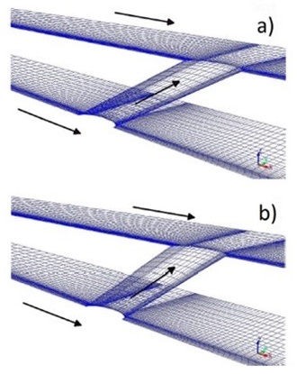
The geometry was then optimised by varying three shape parameters: the injection angle, the lateral hole expansion angle and the downstream compound hole angle. A goal driven optimisation approach was based on a design of experiments table.
The minimisation of the coolant mass flow together with the maximisation of the minimum and average cooling effectiveness were the optimisation objectives. The shape modifications were performed directly in the ANSYS Fluent CFD solver by using the software RBF Morph in the commercial software platform ANSYS Workbench.
There was no need to generate a new geometry and a new computational mesh for each configuration investigated.
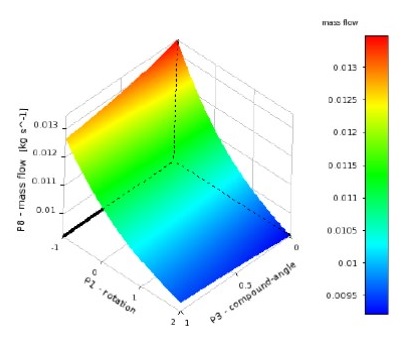
The dependency of the average effectiveness along the plane centreline on the three geometrical parameters was investigated based on the metamodel generated from the design of experiments results.
The goal driven optimisation led to the optimal combination of the three shape parameters to minimise the coolant flow without reducing the cooling effectiveness. The best results were obtained for a geometry with 20o hole angle and 7.5o compound angle injection, leading to a reduction of 15% in the coolant mass flow rate for an enhanced adiabatic cooling effectiveness. The results also showed the preponderance of the centreline angle over the other two parameters.
Click here for more information.